|
|

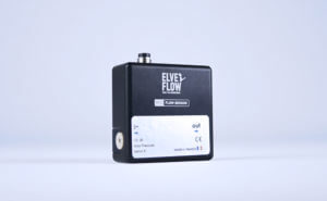
MUX QUAKE VALVE
Microfluidic quake valve controller
Flow switch matrice to control quake and bilayer PDMS microfluidic valves3 port / 2 position valve matrix
Compact arrangement of 16 3:2 valves
Bilayer PDMS valves controller
Automate bilayer binary valve actuation
Precise and fast control
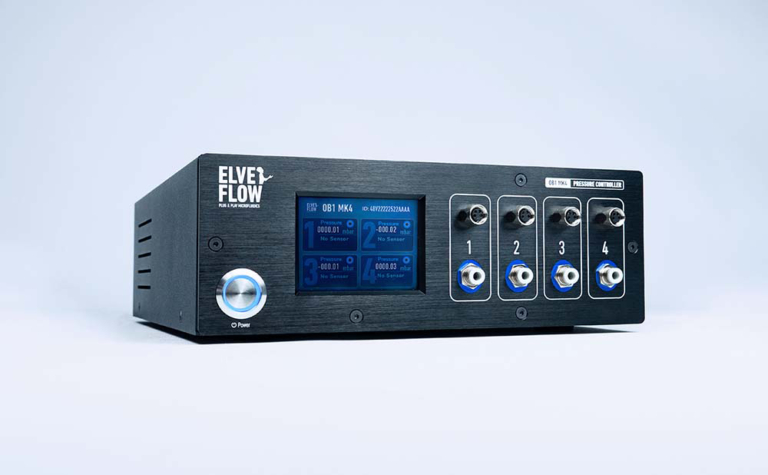
Couple with an OB1 for the highest precision in valve control
Contact us
Features & Benefits
With this matrix of 3:2 valves, you can simply choose when to put your PDMS bilayer valve under pressure. When fed by our OB1 MK3+ pressure controller, the 0.005% stability enables fine control and stable valve position.

Complex Flow Patterns
Our profile editor will allow you to easily program subtle valve patterns and to repeat a set of steps in a loop to automate the most sophisticated protocols.
Setup Synchronization
The MUX Quake offers input/output TTL triggers set to easily synchronize your instrument with any Elveflow® device, microscopes or mechanical shutter. Thus, you can have a full control of all the devices involved in your microfluidic experiment
Other instrument highlights include:
- Plug & play programmable valve sequence
- Fast valve switching (20 ms)
- Fine valve position tuning (when coupled with the OB1 MK3+ pressure controller)
- Flexible: control up to 256 valves by using several MUX Quakes
- Internal/external trigger
- PEEK valves compatible with 10-32 microfluidic fittings.
- ROCKER® valve technology
| MUX QUAKE VALVE CONTROLLER | ||
|---|---|---|
| GENERAL SPECIFICATIONS | ||
| Dimensions without connectors (mm) | 220 x 130 x 130 mm | |
| Valve type in the device | 3-way solenoid valve | |
| Number of valves | 16 valves | |
| Casing material | Aluminium | |
| Mounting orientation | Vertical | |
| Connection type | USB B | |
| Operating temperature | 10°C to 40°C | |
| Operating humidity | 120 to 80% | |
| FLUIDIC SPECIFICATIONS AND CONNECTIONS | ||
| Inlet / outlet connectors | 10-32 UNF | |
| Number of inlets / outlets | 2 inlets and 16 outlets | |
| Wetted materials | PEEK / FKM | |
| Response time of a valve | 10 ms | |
| Maximum supported pressure | 2.5 bar (36 psi) | |
| Internal volume | 20 µL for the volume of a valve chamber | |
| ELECTRICAL SPECIFICATIONS | ||
| Input voltage range, AC | 100 V to 240 V | |
| AC supply frequency | 50 Hz to 60 Hz | |
| Input current, AC | 1 A | |
| Power consumption | 35 W | |
| Safety | IEC / EN 61010-1:2001 | |
| Shutting down power supply | Disconnect AC/DC adapter | |
| CONTROL & MONITORING | ||
| Computer specifications | USB 2.0 port, Intel Pentium II 500 MHz, 1 Go Hard Disk space, 2 Go RAM Windows XP and newer, 32/64 bit. LabVIEW 2011 is required when using LabVIEW libraries | |
| Software control | ESI C++, Python, LabVIEW, Matlab librairies | |
| Trigger | One Trigger IN and one Trigger OUT TTL output | |
• One Trigger IN and one Trigger OUT TTL output.
ESI is Elveflow’s advanced software interface that is built to make every experimenter’s life better. It is perfectly adapted from simple setups to very advanced setup and workflow automation. It integrates several modules that make time-consuming and painful tasks very simple. Elveflow also provides Software Development Kit (SDK) libraries to integrate Elveflow systems using your own code.
ADD your instrument

Configure your instrument with just a click

Automate your setup and communicate with other instruments using the ESI sequencer

Using the ESI interface, you can perform multiple automation functions such as:
– Save the Quake Valve configuration
– Sequence the execution of the Quake Valve with other Elveflow’s instruments using the intuitive scheduler
– Synchronize the Quake Valve with other Elveflow or third party instruments using the device’s external/internal TTL triggers


 Job
Job Collaborations
 Customer
 Other
Other