Application note written by Jesús Manuel Antúnez Domínguez
Microfluidics application note
Published on 21 February 2024
Biolfim Testing Under Flow
Bacteria are able to adhere to most surfaces, and will develop communities over time known as biofilms if the conditions are favorable. Bacterial biofilms are present in many relevant phenomena in our daily lives, both beneficial and detrimental. From the plaque in our teeth to biofouling in ships, chronic infections and environmentally friendly fertilizers; biofilms have many potential applications and ongoing research. However, most of the time, biofilms are studied in bulk cultures, in static or ex situ conditions that do not reflect their dynamic nature. In this guide, biofilms will be grown in a simple microfluidic chip channel for in situ observation of their development under flow conditions to improve environmental relevance, to then test their properties.
Biofilm Testing Applications
- Antibiotic tolerance and resistance
- Bacteria colonization of surfaces
- Bacterial communities evolution
- Microbial species interactions
- Biofilm formation
Experiment setup
Materials
Hardware
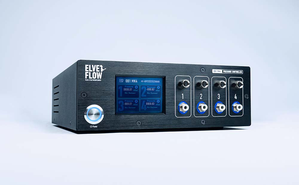
- 1 x OB1 mk4
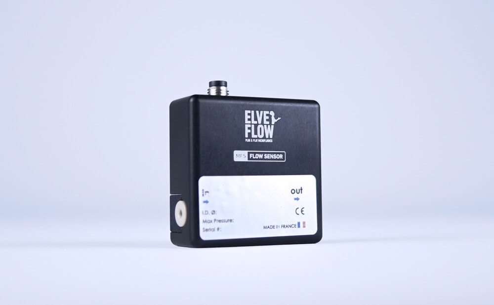
- 1 x MFS2 0-7 µL/min digital flow sensor
- Tubings, fittings and reservoirs
- Fluidic 145 from Microfluidic
- ChipShop
- 20 cm of 100 µm inner diameter microfluidic resistance
- PES syringe sterile membrane filter 33 mm diameter, 0,2 µm pore size (Dutscher, France)
- Microfluidic male and female Luer to ¼”-28 connectors (Darwin microfluidics, France)
- Microscope for observation
- Laminar flow hood
- Spectrophotometer
Chemicals
- Lysogeny Broth (LB) medium (Sigma)
- Bacterial strain: Bacillus subtilis
- Glycerol (optional)[1]
- Manganese chloride (optional)[1]
Software
- ESI software
Design of the Chip

|
Interface Type
|
Mini Luer
|
|---|---|
|
Channel Width
|
50 μm
|
|
Channel height
|
50 μm
|
|
Material
|
TOPAS (COC)
|
|
Surface treatment
|
None
|
|
Lid thickness
|
140 μm
|
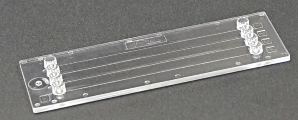
The proposed chip consists of four different straight channel devices. This application used a 50×50 μm section channel. Any other width and length can also work, but the flow rate will have a different speed profile that might affect biofilm formation. TOPAS was chosen for its chemical resistance to ethyl alcohol, which allows the use of common disinfectants in case of leaks or any surface contamination without compromising the integrity of the chip.
[ob1f_rebound]
Quick start guide
Instrument Connection
- Connect your OB1 pressure controller to an external pressure supply using pneumatic tubing and to a computer using a USB cable. For detailed instructions on OB1 pressure controller setup, please read the “OB1 User Guide”.
- Connect the flow sensor to the OB1. For details, refer to “MFS user guide”.
- Turn on the OB1 by pressing the power switch.
- Launch the Elveflow software. The Elveflow Smart Interface’s main features and options are covered in the “ESI User Guide”. Please refer to the guide for a detailed description.
- Press Add instrument \ choose OB1 \ set as MK4, set pressure channels if needed, give a name to the instrument and press OK to save changes. Your OB1 should now be on the list of recognized devices.
- OB1 calibration is required for the first use. Please refer to the “OB1 User Guide”.
- Add the flow sensor: press Add sensor \ select flow sensor \ analog or digital (choose the working range of flow rate for the sensor if you have an analog one), give a name to the sensor, select to which device and channel the sensor is connected and press OK to save the changes. Your flow sensor should be on the list of recognized devices. For details refer to “MFS user guide”.
- Open the OB1 Window.
- In OB1 window, in each of the operating channels, open the sensor related settings, and in the PID values, change both responsiveness and smoothness from 0.001 to 0.008.

Tip from the experts. These parameters are adapted to water, if liquids of different properties and viscosities are used, these values need adjustment for reliable flow control.
Solution Preparation
- For the bacterial suspension: Under the laminar flow hood, fill a reservoir with sterile LB medium and inoculate with overnight culture at 37 °C (optical density > 1) and adjust until optical density reaches 0.1.
- For the growth medium: Under the laminar flow hood, pour fresh LB medium in a reservoir and add any reagents to test. In this case, 1% (w/v) of glycerol and 0.1 mM MnCl2 were added.
- Close the reservoir with a black pressure cap already fitted with sterile 1/32” outer diameter tubing. Cover the pressurized air inlet with tape to avoid contamination until it is connected to the OB1.
Set-up Preparation
- Connect the reservoir cap to the OB1 with pneumatic tubing.
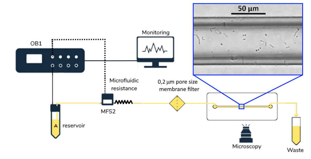
- Connect the reservoir to the MFS2 with 1/32” tubing. Add 20 cm of 100 μm inner diameter microfluidic resistance tubing to the outlet of the flow sensor.
- Connect the end of the microfluidic resistance to 1/32” tubing using a union connector.
Tip from the experts. For more details on the use of resistance to obtain the best performances in terms of flow rate control please refer to the “Flow control tuning” document.
4. Open an individually packed sterile syringe filter. Connect the 1/32” tubing to a male Luer fitting, then add a syringe membrane filter, and then add a female Luer fitting and length of 1/32” tubing.
Tip from the experts. Bacteria will tend to form biofilm inside all the tubing they have access to, which can affect the performance of the MFS2 and clog the resistance tubing over time. In order to protect the microfluidic circuit, a sterile syringe filter can be added inline to avoid bacteria reaching any upstream component and the sterile medium reservoir.
5. Connect the free end of the 1/32” tubing to a mini Luer fitting.
6. Under the laminar flow hood, remove the chip from its packaging, and inoculate it with the bacterial suspension. Use the pipette to completely fill the chip from one end to the other and close the inlets with parafilm to prevent contamination.
7. Connect the chip (since it is a straight channel chip, the inlet and outlet are interchangeable).
8. Connect 1/32” tubing to the chip outlet using a mini Luer fitting, and secure the other end to a safe waste container.
Tip from the experts.The waste contaminated with bacteria constitutes a biohazard. Thus, It must be contained according to the biosafety level of the stain used to ensure safety.
Experiments
1. Leave the microfluidic chip for at least 30 minutes to allow bacteria to attach to the walls. This time can vary according to the strain.
Tip from the experts. After incubation, air will be pushed first through the chip, displacing all the bacterial suspension. Most attached cells will remain attached after pushing air at the proposed flow rate. It is also an option to first purge air from the tubing with the chip disconnected, and reconnect the chip with liquid flowing at a slow drip.
2. Put the chip on the microscope stage. In the OB1 control window, choose the corresponding channel to the reservoir and flow the medium at 5 μl/min until the filter is almost filled with solution.
3. Set the flow rate value to 1 μl/min and let it run until the solution reaches the waste reservoir.
4. Leave the set up running for as long as needed. In this case, considerable biofilm growth was reached after 9 hours. Many biofilms can form in the same channel in one experiment, counting as replicates for the same conditions.
Results of microfluidic biofilm testing
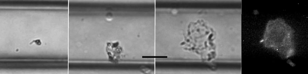
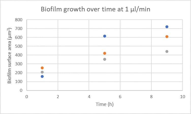
A timelapse of biofilm formation and development under flow was obtained by taking pictures of the same biofilm at different time steps (Figure 1). In the experiment performed, three biofilms formed inside the microfluidic channel, whose sizes were quantified over time (Figure 2). If desired, the reservoir containing growth medium can be changed after biofilm development to test the effects of different substances, for example, antibiotics. Similarly, dyes can be used to stain the bacteria and obtain fluorescent images.
Acknowledgements
This application note is part of a project that has received funding from the European Union’s Horizon 2020 research and innovation programme under grant agreement No. 812780.References
[1] Shemesh, Moshe, and Yunrong Chaia. 2013. “A Combination of Glycerol and Manganese Promotes Biofilm Formation in Bacillus Subtilis via Histidine Kinase KinD Signaling.” Journal of Bacteriology 195(12): 2747–54.
Microfluidics knowledge
Do you want tips on how to best set up your microfluidic experiment? Do you need inspiration or a different angle to take on your specific problem? Well, we probably have an application note just for you, feel free to check them out!

 Job
Job Collaborations
 Customer
 Other
Other