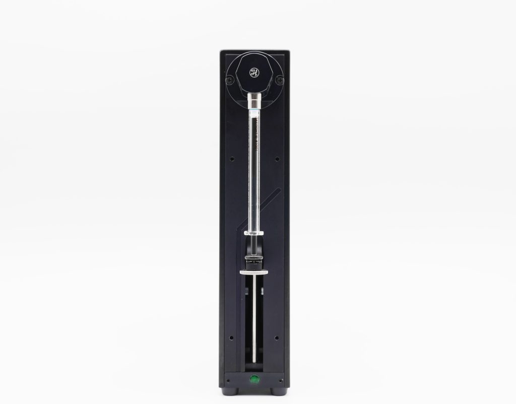
Constant Flow Control System
Controlled flow rate, with nothing to calibrate.Plunger speed sets it, whatever the viscosity.
Your sample changes; the flow rate it sees does not.
Inline pressure, logged live.
A syringe and the software.
A viscous ink, a buffer, a different setup, a new condition to test: the flow rate you set is the one delivered, across eleven syringe sizes from 25 µL to 50 mL.
Features & Benefits
How a flow rate gets held today
The ink has to leave the nozzle at a set rate. The filter has to see a set flow while its resistance climbs. The oil and the water have to reach the junction in a fixed ratio. Every route below holds a flow rate. They differ in what that costs you: what the setup requires, and what has to be re-determined when the liquid, the circuit or the temperature changes.
A peristaltic pump. Rollers squeeze the tubing, so the liquid never meets the mechanism, and a loop can recirculate for days, which suits a recirculating wash or a cooling line. The rate rises and falls as each roller passes. It drifts as the tubing takes a set, so the calibration comes back around mid-campaign.
A rig built in the lab. A stepper motor, a lead screw and a syringe cost an afternoon, and they will hold a rate for a one-off extrusion trial. No port to switch liquids. No status to read when the plunger stalls against a blocked line. And a rate that has to be worked back out from motor steps every time the syringe changes.
Pressure-driven flow control with a flow sensor. Gas pressure on a sealed reservoir gives a smooth, continuous flow. Our pressure controller responds in milliseconds, draws from a reservoir of any size, and runs for as long as the experiment lasts. A flow sensor in the line closes the loop, and the controller trims the pressure to hold the rate you set. It asks for a gas supply, a sensor that suits the liquid, and a calibration before a flow programme. Where the resistance of the line is itself the experiment, a fouling membrane or a packing bed, that sensor sits inside the line that is changing.
A volumetric syringe pump. A plunger of known cross-sectional area advances at a set speed. The volumetric flow rate is set by that movement alone, independent of the liquid’s viscosity and density. A change of liquid costs no calibration. When the resistance downstream rises, in a filter loading up or a nozzle taking up a loaded ink, the pressure rises and the rate stays put. A valve head on the instrument turns a second liquid or a refill into a port move. An inline pressure sensor reads the one variable left free. No compressed gas, no flow sensor in the line. Three limits bound it. At a low rate the plunger advances in discrete steps. Soft tubing stores volume before the far end moves. And delivery runs for at most 100 minutes before the syringe has to refill.
Where the flow rate comes from
The flow rate is fixed by the syringe fitted and how fast the plunger drives it. Viscosity does not enter it, so a glycerol mixture and a buffer leave the syringe at the same rate. No calibration, no correction factor, no trial run to find the real rate. The resistance downstream does not enter it either: a longer line, a narrower chip, a bed packing under flow. What changes is the pressure the circuit demands, spent along the tubing, the valve head and the chip.
A shear-thinning liquid behaves the same way: a viscosity that varies with shear inside the nozzle changes the pressure and leaves the rate alone.
Hold the rate as a filter or a bed loads up
In a fouling filter, a packing bed or a chip inlet that narrows during a run, the resistance is the variable under study. Holding a rate through it means the pressure has to be free to rise. The rate holds in steady state, and the pressure climbs to whatever the circuit needs.
The rate holds as long as the motor can push hard enough. Past that point the plunger stops advancing and the pump flags an overload. A narrower plunger reaches a higher pressure for the same force, so the syringe is chosen around the liquid and the circuit.
See the pressure your chip or plate is taking
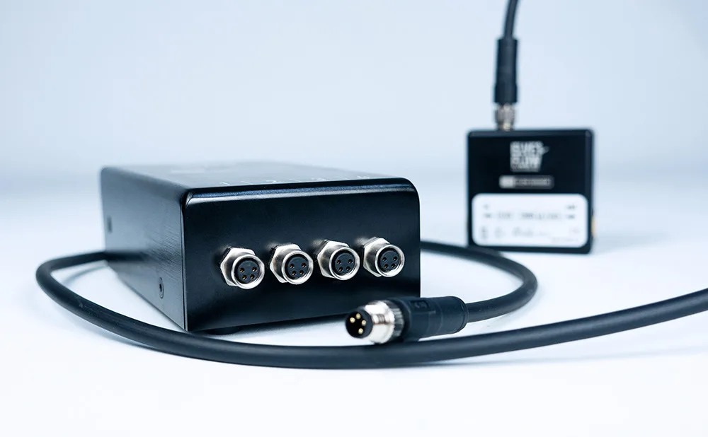
A loaded ink starts to take the nozzle, or a bed compacts near the end of a run. A partial blockage of that kind usually announces itself in the results, a day later. At a constant flow rate it announces itself at once, because pressure is the free variable and therefore the informative one. Put an MPS pressure sensor inline after the valve head and read it with an MSR sensor reader. A rising trace means the resistance rose: a clog, a kinked line, a valve head on the wrong port, a filter reaching the end of its life. The software logs and displays that trace while the run continues. A stall or an overload appears in the pump’s status, and a sequence that reads it can halt on the fault.
A chip, a culture chamber, a multi-well plate or a membrane module each carry a pressure they should not be taken above. A bonded chip can delaminate, a seal can lift, a membrane can tear. With the trace on screen and in the log, that value is known while the run is going on, and the run can be stopped before the device is lost.
In a sequence built in our software, a step compares the measured pressure with a value you set and stops the run when it is passed.
One software, and a trigger to line the setup up
The flow rate, the valve moves and the sequence are set from the Elveflow Smart Interface, from version 3.11 onwards, with the licence included. A rate can change part-way through a stroke, so a purge, a print and a rinse are one saved sequence. Several modules are driven together, each holding its own rate. That is how a fixed ratio between two streams is set. The MSR sensor reader carries a trigger line, so a step can be lined up with another instrument: a microscope, an analyser, or a robotic platform that moves the samples.
Where each route fits
Our pressure controller remains the default answer for a flow rate held smoothly and reactively, from a reservoir of any size, for as long as the experiment lasts. A syringe pump takes the flow rate that has to come from displacement. A liquid whose viscosity is high or changing. A viscosity high enough that a pressurised reservoir no longer reaches the rate you set. A circuit whose resistance rises during the run. A bench with no compressed gas and no sensor to calibrate.
Application
Viscous and non-Newtonian solutions at a set rate
A polymer solution, a hydrogel precursor, a glycerol mixture, an oil. Where the relation between the command and the delivered rate depends on the fluid, every new formulation costs a calibration. So does a shift in room temperature, since viscosity moves with it. Both disappear when a plunger sets the rate. On our syringe pump the number you set is the number the circuit receives, for a viscous stock as for a buffer. A shear-thinning liquid is no different: the delivered rate holds while the viscosity changes. The syringe and the valve head are specified around the liquid, because a thicker liquid asks more of the whole path.
Constant flow into a rising resistance
A packed bed, a membrane at constant flux, a depth filter, a chip inlet that collects particles as the run goes on. The resistance is what the experiment measures, so the instrument has to hold the rate and let the pressure follow. Our syringe pump does that in steady state. An inline pressure sensor turns the rise into a logged curve, which is the resistance measurement itself. Nothing sits in the fouling line to be read or calibrated. Delivery runs for at most 100 minutes before a refill, so a longer study is built from bounded runs, each starting from a known state.
Extrusion for printing and fibre spinning
A bioink, a ceramic paste, a hydrogel, a polymer solution drawn into a fibre. The deposited width follows the extrusion rate and the head speed together. A shear-thinning ink changes viscosity as it passes the nozzle. Setting the rate from displacement means the same command gives the same rate, whatever the ink does inside the nozzle. The last layer of a build matches the first. Prints are short, which suits a run bounded by the stroke. Loading the cartridge and metering the two parts of a formulation in a fixed ratio are volume questions, and our volume dispensing page covers them.
Electrospinning, electrospray and infusion to a mass spectrometer
At the tip, the jet is set by the balance between the field and the liquid arriving. That arriving rate has to hold for the whole acquisition. A polymer solution in a volatile solvent is exactly the liquid that makes a measured loop awkward, and the rates involved are low and steady. Our syringe pump sets that rate from the plunger. A closed path of glass and fluoropolymer holds the solvent. No gas line has to be routed onto a bench already carrying a high-voltage supply and a collector. The valve head reaches a second solution for a coaxial tip or a rinse between samples.
Flow-rate ratio with a viscous phase
Two streams meeting at a junction: a coaxial fibre, a droplet generator, an on-chip dilution. The ratio between the two rates sets the outcome. Two modules run together, each holding its own rate, so that ratio comes from the two plunger speeds. It does not shift when one phase is a loaded polymer or a viscous oil. For a standard aqueous and oil emulsion, pressure-driven flow control stays our recommendation, and the application packs built around it are the shorter path.
| PSD – Microfluidic Syringe Pump | |||||
|---|---|---|---|---|---|
| Syringes and volume | |||||
| Syringe volumes | 25, 50, 100, 250, 500 µL and 1, 2.5, 5, 10, 25, 50 mL. | ||||
| Stroke length: 60 mm. Full-stroke time: 2 s to 100 min. | |||||
| Delivered-volume resolution | 48,000 steps per stroke. | ||||
| Accuracy and stability | |||||
| Volume accuracy | ±1% at full stroke on every syringe. | ||||
| Dispense-to-dispense stability | down to 0.05% at full stroke. | ||||
| Minimum volume increment | 0.002% of the syringe volume, one motor step. | ||||
| Valve and routing | |||||
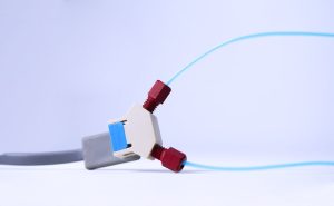
| Valve heads | distribution heads with up to eight ports, and two- or three-port heads for simpler paths. | ||||
| Valve drive | stepper motor with optical encoder, about 95 ms from one port to the next. | ||||
| Fittings ¼″-28. Nominal fluid path diameter 1.524 mm. | |||||
| Fluids and materials | |||||
| Wetted materials | borosilicate glass, PTFE, PFA, CTFE and ceramic, with a PTFE or UHMW-PE plunger tip. | ||||
| Valve materials | CTFE, PTFE, ETFE, ceramic. | ||||
| Software and control | |||||
| Elveflow Smart Interface (ESI), supported from version 3.11; licence included. | |||||
| Communication | RS-232, RS-485 or CAN. | ||||
| Saved sequences on the module; ramps, loops, flow-rate change during a stroke, backlash compensation; stall and overload reported over the serial link. | |||||
| Physical and electrical | |||||
| 24 VDC, external power supply included. Delivered set: pump with casing, power supply, cable set and ESI licence. | |||||
| Operating conditions | 15 to 40 °C, 20 to 95% relative humidity, non-condensing. | ||||
Accuracy and stability figures measured with deionised water at 22 °C.
Frequently Asked Questions
The Elveflow PSD is a syringe pump for research and instrument work. In flow rate control it advances a plunger of known cross-sectional area at a set speed. The flow rate through a chip, a column, a membrane or a nozzle then comes from the geometry of the syringe, with no calibration step between one liquid and the next. Viscosity and downstream resistance change the pressure the circuit demands. They leave the displaced rate alone. Eleven syringe sizes from 25 µL to 50 mL, a valve head with up to eight ports and an inline pressure reading cover the work on one instrument.
The Elveflow PSD arrives configured. The syringe size and the valve head are chosen with you, and the licence to drive the pump from the Elveflow Smart Interface is part of the order. Nothing else has to be sourced to run it: no compressed gas, no flow sensor in the line.
You set a flow rate in the software, and the Elveflow PSD converts it to a plunger speed through the syringe’s cross-sectional area. The displacement sets the rate, so there is nothing to calibrate before a run and nothing to adjust when the liquid changes. The lower rates come from the smaller syringes, because a syringe’s rate range scales with its volume. Two things matter at the bottom of that range. The plunger advances in discrete motor steps, 48,000 across a full stroke, so delivery arrives in small increments. And soft tubing stores volume as it comes up to pressure, so the far end lags the command by a settling time. A smaller syringe and stiffer tubing both shorten that lag.
Take the smallest syringe that covers your highest rate. The rate range scales with the syringe volume, so a large syringe reaches a high rate but delivers a low one in coarse increments. Accuracy on the Elveflow PSD also improves with the fraction of stroke used. Eleven sizes run from 25 µL to 50 mL. The second half of the choice is duration, since the volume you get between refills is the syringe volume. Where the smaller syringe cannot hold enough for the run, refilling from a reservoir port covers the rest, with a pause each time.
Yes, once the flow is steady and as long as the motor can push hard enough. The Elveflow PSD sets a plunger speed, so a rising downstream resistance appears as a rising pressure. The delivered rate stays where you set it. That is what suits it to a packed bed, a membrane or a chip inlet that narrows during the run. Past what the motor can push, the plunger no longer advances, and the pump flags an overload that the software shows. The shortfall in delivered rate is not measured, so the useful warning comes from the pressure. An Elveflow MPS sensor read by an MSR sensor reader shows it climbing well before that point.
Delivery runs for at most 100 minutes on the Elveflow PSD. When the syringe empties, the plunger returns to refill and delivery pauses while it does. Inside a saved sequence that refill is one of the steps, drawing from a reservoir port on the valve head. A print, a spinning run or a filtration step is built from bounded runs. Where a flow rate has to be held for hours without a pause, the better instrument is the Elveflow OB1 pressure controller, drawing from a reservoir of any size. It stays our recommendation for that work.
Yes, and displacement is the reason. The Elveflow PSD displaces a known volume per unit time. A glycerol mixture, a polymer solution or a shear-thinning ink runs at the rate you set, with no calibration when the formulation changes. What viscosity changes is the pressure the circuit demands, and that is spent along the tubing, the valve head and the chip. A thicker liquid asks more of the whole path, so the syringe and the valve head are specified around it.
At a set flow rate the pressure is the dependent variable, so the Elveflow PSD has no pressure setting. What appears is what the circuit demands to accept that rate, spent along the tubing, the valve head and the chip. A ceiling does exist, and three parts of the system set it: the drive’s force, the syringe’s own rating, and the valve head’s. Whichever is lowest is the one you meet. It moves down as the syringe gets wider, because the same force spreads over a larger plunger face. A high rate through a fine nozzle is small-syringe work. No single maximum figure is published, because the ceiling belongs to the configuration. In practice the binding limit is often the device downstream, a chip or a plate with its own rating, which is the reason to read the pressure inline. Send us the syringe, the valve head and the circuit, and we will confirm the ceiling for that combination.
Yes, and at a constant flow rate pressure is the variable worth reading. Because the Elveflow PSD sets the rate and not the pressure, a rising pressure means the resistance rose. That is a nozzle taking up a loaded ink, a kinked line, a valve head on the wrong port, or a filter at the end of its life. Put an Elveflow MPS pressure sensor inline after the valve head and read it with the MSR sensor reader. The software logs and displays the trace while the run continues. The same reading protects the device downstream. Your chip, chamber or plate has its own pressure limit. The measured pressure is on screen and in the log while the run continues, so the run can be stopped before the device is damaged. The same value can trigger that stop: in an Elveflow Smart Interface sequence, a step compares the reading with your limit and halts the run when it is passed. The pump also flags a stall or an overload, so a sequence that reads that flag can stop on the fault.
Yes. Several Elveflow PSD modules run from the same software, each holding its own flow rate. A ratio between two streams comes from the two plunger speeds, and it holds when one of the liquids is viscous. A trigger line on the MSR sensor reader ties the run to the instruments around it: a microscope, an analyser, or the robotic platform moving your samples. Elveflow Smart Interface sequences are built from rate changes, valve moves and loops, and a saved sequence comes back with one command.
Cleaning runs as a sequence on the Elveflow PSD, since the plunger reverses under the same control it advances. Draw solvent through one port of the valve head, send it to waste through another, repeat as a loop. That matters most after a polymer solution or an ink, where a residue left in the path changes the resistance of the next run. The wetted path is borosilicate glass, PTFE, PFA, CTFE, UHMW-PE and ceramic, and the valve head is CTFE, PTFE, ETFE and ceramic.
Support starts at version 3.11 of the Elveflow Smart Interface, and the licence is part of the order. The interface holds the flow rate, builds and stores sequences, and timestamps the run as it goes. Fit an MPS sensor and an MSR reader and the pressure trace appears next to it, and a sequence step can test that reading and halt the run above a limit you set. The Elveflow PSD also takes commands straight from your own code, over RS-232, RS-485 or CAN.
Yes. The Elveflow PSD is driven from the Elveflow Smart Interface, the same software that runs the rest of the range, so it joins a bench already built around Elveflow instruments with no second application to learn and no separate control setup. What you already know about building a sequence carries over.
It comes down to what makes your flow rate hard to hold. The liquid and the circuit point to the Elveflow PSD syringe pump: a viscosity that is high or changing, a resistance that rises during the run, a bench with no compressed gas. The rate comes from the plunger, with no calibration between one liquid and the next. If you need a flow rate held smoothly and reactively for hours, from a reservoir of any size, the Elveflow OB1 pressure controller is the fit. That covers cell perfusion and long low-flow runs, and it stays our default recommendation. Plenty of setups run both, one for the rate that comes from displacement and one for the rate that comes from pressure. Send us your protocol and we will settle the choice on your own configuration.
Use the contact form and tell us three things: the flow rates you need to hold, the liquids you push, and what sits downstream. We will reply with a configuration, syringe, valve head and pressure sensor, and a quote for the Elveflow PSD around it.



 Job
Job Collaborations
 Customer
 Other
Other
