Atencia et al. (2009) overcome this problem designing what they have called a “microfluidic palette.” In particular, this device enables both to deliver soluble factors without shear stress and to generate controlled gradients with different spatial locations. The dynamic control of the generated gradients is achieved by decoupling convective flows from diffusion in the main chamber of the device. The striking point is that this is achieved without the means of any membrane or gel. In the following sections, the principles underlying this device will be discussed.
Figure 1 shows a schematic of a cross channel gradient generator; the T junctions at the end of the microchannel are the convection units. In order to decouple convection through the side channel from diffusion across the main channel, bulk flow rates through the inlet and the outlet have to be matched. Pretending that one convection unit is the carrier of a constant solute concentration while the other unit carries buffer, this allows to create a gradient across the microchannel which remains constant as long as the flows and concentrations of solute at each convection unit remain the same.

Figure 1
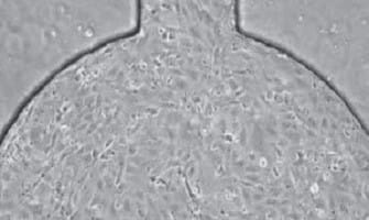
This basic principle is extended to a two-dimensional format in the microfluidic palette where several convection units revolve around a circular microchamber, each unit acting as a perfect sink or source of a given solute. In particular, in this device the aforementioned prerequisite of bulk flow matching is achieved by balancing the pressure between all access ports (Figure 2).
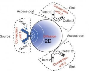
Figure 2
Moreover, in order to obtain stable gradients, three main features have been implemented in the design of the device. First of all, the main microfluidic chamber has been strengthened with a rigid substrate in order to avoid transient flows related to deformations. Furthermore, the outlets of the convection units have been merged through low resistance rigid channels on chip. Finally, a network of under-vacuum microchannels has been implemented in order to remove bubbles from the device.
More specifically, the device is made up of a main microfluidic chamber, where the gradient is developed, and a platform where three microchannels are used to deliver solutes using fluid flow at the three convection units (figure 3). The microfluidic chamber is a glass cylinder (1.5 mm in diameter and 3-20 µm of thickness) with three radially distributed inlets which work as sources and sinks for the load and removal of the solutes. The delivery platform is two-layered: one is made of PMMA whereas the other one is made of PDMS. The latter is used as a sealing gasket between the glass of the main microfluidic chamber and the PMMA layer. Furthermore, in the PMMA layer there is a network of channels which are not communicating with any other network of the device. These channels are used to purge bubbles from the main fluidic network by applying vacuum which generates a negative pressure on the PMMA/PDMS interface which binds the two layers as well. Sample loading is achieved using external syringe pumps with matched flow rate in order to avoid convection in the chamber.

Figure 3
In conclusion, the microfluidic palette is a device which allows to develop via diffusion stable chemical gradients in its main microfluidic chamber. Furthermore, these gradients can be tuned in space and time with high precision by only varying the relative positions of the source and the sink. In fact, it is also possible to overlap several gradients inside the chamber. Finally, repeated measurements and experiments have proven the robustness and repeatability of the system over time.
Moving over, here will be briefly described a microfluidic gradient generator designed by Chang et al.(2014). This device is made of PDMS with a built-in polycarbonate (PC) membrane as a gas diffusion barrier (Figure 4). Chemical gradients are generated within the device using an arrangement of serpentine channels. The main strength of this system lies on its simplicity of use and manufacture, plus it can be placed inside conventional cell incubators for optimized cell culture conditions. The device is made up of two PDMS layers: the upper one is placed in the chamber for chemical reaction whereas in the lower one there is the cell culture chamber where gradients are established. These two layers are divided by a PDMS membrane (100 µm) in order to prevent contamination of the cell environment by the reagent in the upper layer of the chip. Furthermore, an additional PC membrane is placed inside the upper PDMS layer in order to minimize gas diffusion. As said before, two inlets and a network of serpentine channels are used to develop chemical gradients inside the cell culture chamber, which can be tuned by editing the design and geometries of the channels.
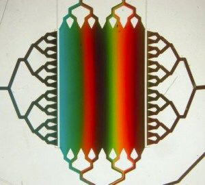
Figure 4
Due to its particular design, the chemical gradient is developed across the width of the cell culture chamber which means perpendicularly to the perfusion flow direction. Moreover, the creation of gradients was proven to be stable over time and repeatable thanks to optical observations with dyers and fluorescent media and comparison with simulation made with COMSOL software (Figure 5).

Figure 5






 Job
 Collaborations
 Customer
 Other